Overshoot and Undershoot (DBL)
This instance operates on the waveform data type when the Y data values are double-precision, floating-point numeric values. Use the I8 instance of this VI with integer data to reduce the size of the data and the memory usage.
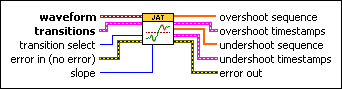
 | waveform is the waveform to measure.
| ||||||||||||||||||||||||||||
 | transitions contains information about the transitions in the waveform. Use the Find Transitions VI to generate this cluster.
| ||||||||||||||||||||||||||||
 | transition select sets whether to identify overshoot and undershoot in the regions before or after each transition.
| ||||||||||||||||||||||||||||
 | error in describes error conditions that occur before this node runs. This input provides standard error infunctionality. | ||||||||||||||||||||||||||||
 | slope specifies the direction of the transitions for which you want to return measurements.
| ||||||||||||||||||||||||||||
 | overshoot sequence returns an array of the overshoot values for local maximums associated with the types of transitions you specify using slope and transition select. Overshoot measures the height as a fraction of the amplitude of the signal. Refer to the Details section of this topic for more information about how this VI calculates overshoot. | ||||||||||||||||||||||||||||
 | overshoot timestamps returns timing information about the waveform that allows you to identify the times at which measurements in the corresponding sequence occur.
| ||||||||||||||||||||||||||||
| undershoot sequence returns an array of the undershoot values for local minimums associated with the types of transitions you specify using slope and transition select. Undershoot measures the height as a fraction of the amplitude of the signal. Refer to the Details section of this topic for more information about how this VI calculates undershoot. | ||||||||||||||||||||||||||||
| undershoot timestamps returns timing information about the waveform that allows you to identify the times at which measurements in the corresponding sequence occur.
| ||||||||||||||||||||||||||||
 | error out contains error information. This output provides standard error out functionality. |


Overshoot and Undershoot (I8)
This instance operates on the waveform data type when the Y data values are 8-bit signed integers.
| waveform is the waveform to measure.
| ||||||||||||||||||||||||||||
| transitions contains information about the transitions in the waveform. Use the Find Transitions VI to generate this cluster.
| ||||||||||||||||||||||||||||
| transition select sets whether to identify overshoot and undershoot in the regions before or after each transition.
| ||||||||||||||||||||||||||||
| error in describes error conditions that occur before this node runs. This input provides standard error infunctionality. | ||||||||||||||||||||||||||||
| slope specifies the direction of the transitions for which you want to return measurements.
| ||||||||||||||||||||||||||||
| overshoot sequence returns an array of the overshoot values for local maximums associated with the types of transitions you specify using slope and transition select. Overshoot measures the height as a fraction of the amplitude of the signal. Refer to the Details section of this topic for more information about how this VI calculates overshoot. | ||||||||||||||||||||||||||||
| overshoot timestamps returns timing information about the waveform that allows you to identify the times at which measurements in the corresponding sequence occur.
| ||||||||||||||||||||||||||||
| undershoot sequence returns an array of the undershoot values for local minimums associated with the types of transitions you specify using slope and transition select. Undershoot measures the height as a fraction of the amplitude of the signal. Refer to the Details section of this topic for more information about how this VI calculates undershoot. | ||||||||||||||||||||||||||||
| undershoot timestamps returns timing information about the waveform that allows you to identify the times at which measurements in the corresponding sequence occur.
| ||||||||||||||||||||||||||||
| error out contains error information. This output provides standard error out functionality. |

Overshoot and Undershoot Details
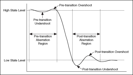
The following illustration shows the overshoot and undershoot in a single negative transition.
The following illustration shows the overshoot and undershoot in a single positive transition.
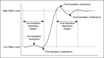
Pre-transition Measurements
To calculate pre-transition overshoot and undershoot for each transition, LabVIEW searches for a local minimum and maximum in the pre-transition aberration region immediately preceding the beginning of the transition. The pre-transition aberration region is defined as the minimum of 3*(end time – start time) and (current transition start time – previous transition end time) / 2. If the transition to measure is the first in the waveform, the interval is defined as the minimum of 3*(end time – start time) and (start time – beginning of the waveform).
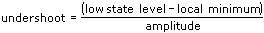
If slope is falling, LabVIEW calculates the pre-transition undershoot using the following equation:
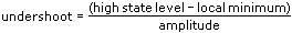
If slope is rising, LabVIEW calculates the pre-transition undershoot using the following equation:
If slope is falling, LabVIEW calculates the pre-transition overshoot using the following equation:
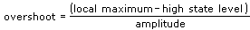
If slope is rising, LabVIEW calculates the pre-transition overshoot using the following equation:
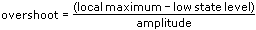
where the state levels and amplitude are defined in the transitions input.
Post-transition Measurements
To calculate post-transition undershoot and overshoot for each transition, LabVIEW searches for a local minimum and maximum in the post-transition aberration region immediately following the end of the transition. The post-transition aberration region is defined as the minimum of 3*(end time – start time) and (next transition start time – current transition end time) / 2. If the transition to measure is the last in the waveform, the interval is defined as the minimum of 3*(end time – start time) and (end of the waveform – end time).
If slope is falling, LabVIEW calculates the post-transition undershoot using the following equation:
If slope is rising, LabVIEW calculates the post-transition undershoot using the following equation:
If slope is falling, LabVIEW calculates the post-transition overshoot using the following equation:
If slope is rising, LabVIEW calculates the post-transition overshoot using the following equation:
where the state levels and amplitude are defined in the transitions input.
Example
Refer to the Overshoot Demo VI in the labview\examples\Jitter Analysis\Level Measurements directory for an example of using the Overshoot and Undershoot VI.
source : http://zone.ni.com/reference/en-XX/help/373270B-01/lvjitterphtk/overshoot_and_undershoot/


0 komentar:
Post a Comment